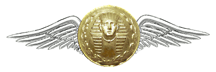

Figure 1-5. – FLAPERON CONTROL SYSTEMS
- Wing fold flaperon interlock switch
- Flaperon control linkage
- Right wing flaperons
- Flaperon actuator (right wing)
- Flaperon pop-up valve
- Wing-fold‚ interlock mechanism
- Filter
- Crossover cables Flaperon pop-up mechanism and cylinder
- Left wing flaperons
- 1Flaperon control linkage
- Flaperon actuator (left wing)
- Crossover cables
- Pushrods Left wing flaperons
- Throttle quadrant
Longitudinal control systems control pitch about the lateral axis of the aircraft. Many aircraft use a conventional elevator system for this purpose. However, aircraft that operate in the higher speed ranges usually have a movable horizontal stabilizer. Both types of systems are discussed in the following text.
ELEVATOR CONTROL SYSTEM – A typical conventional elevator control system is operated by the control stick in the cockpit, and is hydraulically powered by the elevator power mechanism. The operation of the elevator control system is initiated when the control stick is moved fore or aft. When the stick is moved, it actuates the control cables that move the elevator control bell crank. The bell crank transmits the movement to the power mechanism through the control linkage. In turn, the power mechanism actuates a push-pull tube, which deflects the elevators up or down. If the hydraulic system fails, the cylinder can be disconnected. In this condition the controls work manually through the linkage of the mechanism to actuate the elevators.
HORIZONTAL STABILIZER CONTROL SYSTEM – Horizontal stabilizer control systems are given a variety of names by the various aircraft manufacturers. Some aircraft systems are defined as a unit horizontal tail (UHT) control systems, while others are labeled the stabilator control system. Regardless of the name, these systems function to control the aircraft pitch about its lateral axis.
Source: http://www.tpub.com


